This browser is no longer
supported. Upgrade to Microsoft Edge or switch to a supported browser, like Chrome, Safari, or Firefox,
to explore the HanSeal Tech website.
We're sorry for the inconvenience.
Home > Technical Resources > Seal Design Guide
A practical engineering reference for designing and integrating spring energized seals into demanding sealing applications.
Seal performance depends on more than the sealing material alone. Spring load, lip geometry, pressure, extrusion clearance, gland design, mating hardware and installation conditions all affect how a spring energized seal performs in service.
This guide outlines the main design factors to consider when selecting or developing a spring energized seal for static, reciprocating, oscillating, rotary or other demanding applications.

A spring energized seal is a system, not a single component. These seven factors interact with each other — change one and the requirements of the others may shift.
These factors should be evaluated together rather than in isolation.
A change in one area can shift the requirements of the others.
The right combination is defined by the application — not by a universal standard.
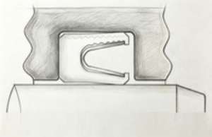
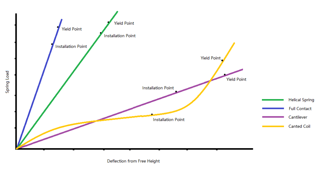
Spring energizer selection should be based on the required sealing force, available deflection, motion, friction requirements, operating environment and available gland space. Different spring geometries provide different load and deflection characteristics, so the spring should be selected as part of the complete seal design rather than as an isolated component.
| Spring Characteristic | Design Consideration |
|---|---|
| Spring Load | Initial sealing force, friction and wear |
| Deflection Range | Wear compensation, runout and dimensional variation |
| Spring Geometry | Available space, motion and sealing configuration |
| Material |
Temperature, media and corrosion requirements |
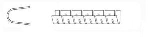
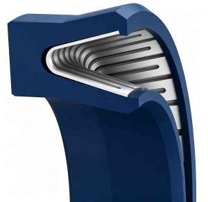
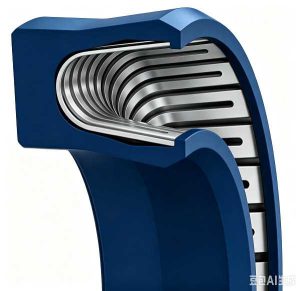
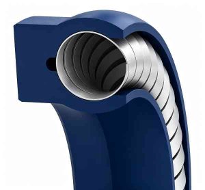
Hansealing manufactures multiple spring energizer configurations, including Helical, Canted Coil, Cantilever V, Cantilever U, Full Contact and Detached Leg designs. The appropriate configuration depends on the sealing position, motion, required load, available space and operating environment.
Spring load — Spring load affects the initial contact force between the seal lip and mating surface. Increasing spring load can improve initial sealing contact, but may also increase friction and wear. The appropriate load is therefore a balance between sealing reliability, friction and service life.
Deflection range — Deflection range determines how much dimensional variation the spring can accommodate while maintaining sealing contact. It becomes particularly important where seal wear, shaft runout, bore variation or assembly tolerances are present.
| Spring Type | Load Characteristic | Typical Use |
|---|---|---|
| Cantilever Spring | Moderate and progressive load, high flexibility at the lip edge | Dynamic sealing, highly viscous and abrasive fluids |
| Canted Coil Spring | Relatively flat and moderate load over a broad deflection range | Friction-sensitive sealing, small diameters and cross-sections |
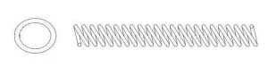
| Helical Spring | Can provide relatively high spring load within a compact deflection range, making them useful for applications where strong energizing force and dimensional stability are important. | Low pressure, vacuum and cryogenic sealing |
The lip profile controls how the seal contacts the mating surface and has a direct influence on friction, lubrication, wear and resistance to contamination. Three common profiles are beveled/chamfered, scraper and rounded/beaded/radiused, while application-specific geometries can be developed when standard profiles are not suitable.


A widely used general-purpose profile for dynamic and static sealing.
The angled lip creates a defined contact area with the mating surface and can provide a good balance between sealing contact, friction and lubrication.
It is also relatively easy to install when the gland and seal geometry are properly designed.

A scraper profile is commonly considered where abrasive particles, dust or other contamination may reach the sealing interface.
The scraping edge helps limit particle accumulation around the sealing lip and can reduce contamination-related wear.
Installation requires particular care because the thinner lip geometry can be more sensitive to damage.

The rounded contact area can maintain a broader lubricating film between the seal and mating surface, which may reduce contact stress and wear in suitable dynamic applications.
However, the same geometry may allow more fluid migration than a sharper sealing edge in some high-speed reciprocating applications and is generally less suitable for abrasive media.
For high-pressure applications, provide the operating pressure, temperature, extrusion clearance and hardware drawing so the seal configuration can be evaluated for the actual application.
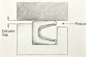
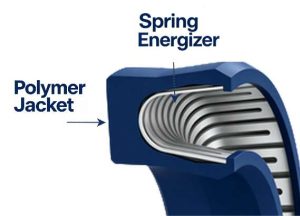
The extrusion gap is the clearance between the seal and the adjacent hardware. Under pressure the polymer jacket tends to flow into this gap. If the gap is too large or the pressure too high for the material’s modulus, the seal extrudes and fails. Reducing the gap is often the most effective way to extend seal life at high pressure.
Increasing the seal’s radial cross-section provides more material to resist extrusion. A taller seal has a longer extrusion path before material reaches the gap. The trade-off is higher installation force and larger gland dimensions.
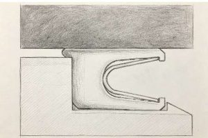
Backup rings or anti-extrusion elements can be used when the available hardware clearance cannot be reduced sufficiently. Material selection should consider pressure, temperature, media compatibility and the required extrusion resistance.
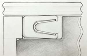
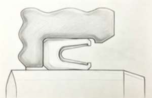
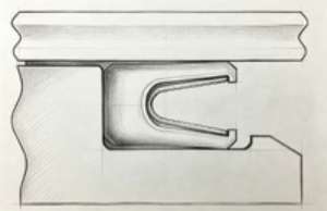
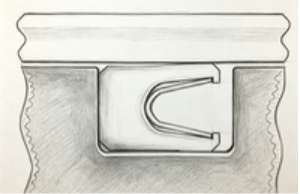
Gland configuration directly affects seal installation, retention and resistance to distortion. The most common configurations are split, step and closed glands.
A split or separable gland allows the seal to be installed without stretching it over the shaft or compressing it into a closed groove.
This configuration is particularly useful for larger seals and applications where protecting the sealing lip during installation is important.
A step gland uses a reduced gland wall or shoulder to help retain the seal while allowing installation in a non-split housing.
It is commonly considered when a split housing is not practical and the seal can be installed from the heel side.
A closed gland provides a fully enclosed groove around the seal. This configuration may require the seal to be stretched or compressed during installation, so seal dimensions, installation procedures and protective tooling should be considered during the design stage.
Sharp corners, threads, keyways and other discontinuities should not be allowed to damage the sealing lip during installation.
The gland should be designed together with the seal, not selected independently. Groove width, depth, seal cross-section, extrusion clearance, pressure direction and installation method should all be considered together.
The appropriate configuration depends on pressure direction, motion, clearance and gland geometry.
Symmetrical profiles can generally be used for either rod or piston sealing and simplify seal orientation and inventory.
They are useful where installation flexibility and a common seal configuration are more important than optimizing the profile for one specific direction of movement.
Non-symmetrical profiles are designed around a defined sealing direction or application.
They can provide additional support or stability in demanding dynamic applications when the seal profile and gland are designed together.

Correct installation is essential to achieving the intended sealing performance. Even a properly designed seal can be damaged during assembly if the installation path or tooling is not suitable.
Mating hardware is part of the seal design. Shaft or bore dimensions, surface condition, hardness, dimensional tolerance and available clearance can all influence sealing performance.
Before installation, inspect the shaft, bore and gland for burrs, sharp edges, threads, keyways and surface damage that could contact the sealing lip.
Mating surfaces should also be checked for dimensional accuracy and suitable surface condition before the seal is installed.
Spring energized seals may be installed lips-first or heel-first depending on the seal profile and gland configuration.
Lips-first installation requires the sealing lip to pass over the mating hardware and therefore requires careful control of edges, transitions and installation tooling.
Heel-first installation can reduce the risk of damaging the sealing lip, but requires a gland configuration that allows the seal to be positioned correctly.
Tapered sleeves, installation cones, guide tools and protective caps can help prevent the seal lip from contacting sharp edges, threads or grooves during assembly.
When the seal must pass over threads, grooves, keyways or other discontinuities, use an appropriate installation sleeve, guide or protective method.
Avoid forcing the lip over sharp edges.
The seal should remain properly seated in the gland during installation. Twisting, rolling or uneven deformation can change the lip position and spring loading, potentially causing leakage or premature wear.
A reliable seal design starts with the operating conditions.
Before selecting a standard seal or requesting a custom design, define the main application parameters below.
| Step | Consideration | Key Questions |
|---|---|---|
| 1 | Sealing Position | Rod / Shaft, Piston / Bore, Face, Shaft & Bore, or other configuration |
| 2 | Motion | Static, Reciprocating, Oscillating, Rotary, Single Acting, Double Acting, Helix |
| 3 | Pressure | Operating pressure, pressure direction and pressure fluctuations |
| 4 | Temperature | Minimum, continuous and maximum operating temperature |
| 5 | Media | Fluid, gas, chemical, vacuum or other media |
| 6 | Speed / Cycle | Shaft speed, reciprocating speed, frequency and expected cycle life |
| 7 | Spring Energizer | Required spring configuration, load, deflection and available space. |
| 8 | Lip | Beveled / Chamfered, Scraper, Rounded / Radiused or custom |
| 9 | Seal Material | PTFE or other polymer, grade, filler and required chemical resistance |
| 10 | Gland & Hardware | Groove dimensions, extrusion clearance, shaft/bore dimensions and surface condition |
These parameters should be evaluated together. A change in pressure, temperature, motion or hardware clearance may require a different spring, lip profile, material or gland configuration.
Standard spring energized seal profiles cover a wide range of applications. However, some operating conditions require a seal designed specifically for the application.
Because Hansealing manufactures its spring energizers in-house, the spring can be developed together with the seal geometry rather than selected only from an externally available spring range.
This allows closer control of spring load, deflection, dimensions, spring material and production requirements when a standard configuration is not suitable.
Custom design may be required when:
| What to Send | Why It Helps |
|---|---|
| Application drawing (PDF / CAD) | Shows gland dimensions and hardware geometry |
| Operating conditions | Pressure, temperature, motion type and speed |
| Media | Determines polymer and spring material compatibility |
| Existing seal sample | Helps identify the current design when replacing a seal |
| Performance requirements | Expected service life, leakage limits and special conditions |
Choose the path that fits your situation.
📄
Already have a drawing, sample or existing part?
Send us your:
We can review the requirements and provide a quotation for replacement or new production.
🔧
Developing a new product or sealing system? Share your operating conditions:
Our engineering team can evaluate the sealing conditions and recommend a suitable spring energized seal configuration, including spring energizer, lip geometry, material and gland requirements.